「RapberryPi Zero Wで2.4 inch Full Color LCDに表示」でLCDに画像を表示しましたが、RapberryPi Zero Wで2.4 inch Full Color LCDを使ってタッチパネルから入力します。
Raspberry PI 3と2.4 inch Full Color LCDの接続
RapberryPi Zero Wと2.4 inch Full Color LCDを次のように接続します。「T_IRQ」を接続するとタッチしたときに、コールバック関数を呼び出す処理が可能となります。
| RapberryPi Zero | LCD |
|---|---|
| SCLK_1 (GPIO21) | T_CLK |
| CE_1 (GPIO17) | T_CS |
| MOSI_1 (GPIO20) | T_DIN |
| MISO_1 (GPIO19) | T_DO |
| GPIO26 | T_IRQ |
| 3.3V Power | VCC |
| Ground | GND |
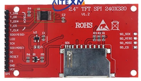
LCDの裏面を次に示します。タッチスクリーン・コントローラ「XPT2046」(緑枠線)がみえます。
SPIの有効化
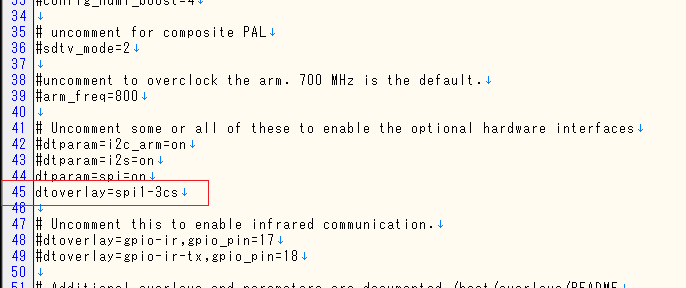
タッチパネルから入力するためにもう一つのSPIデバイスを登録します。構成ファイル「/boot/config.txt」に次のコードを追加します。
dtoverlay=spi1-3cs
変更した構成ファイル「/boot/config.txt」を次に示します。
タッチパネル入力プログラムの作成
タッチスクリーン・コントローラ「XPT2046」を使ったタッチパネル入力プログラム「 touch-test.py」は「XPT2046-Python」のテストプログラムを使用します。githubに含まれる「xpt2046」は「touch-test.py」と同じフォルダに置きます。
- 19行目でコールバック関数「touchscreen_pres」を設定します。
- 22行目で定期的にタッチパネルのx,yデータを表示します。
touch-test.py
from xpt2046 import Touch
from gpiozero import Button, DigitalOutputDevice
import board
import busio
from time import sleep

# touch callback
def touchscreen_press(x, y):
    print(x,y)

cs = DigitalOutputDevice(17)
clk = board.SCLK_1		# same as writing 21
mosi = board.MOSI_1	# same as writing 20
miso = board.MISO_1	# same as writing 19
irq = Button(26)

spi = busio.SPI(clk, mosi, miso)	# auxiliary SPI

xpt = Touch(spi, cs=cs, int_pin=irq, int_handler=touchscreen_press)

while True:
    print(xpt.get_touch()) # to get the (x, y) coords when you desire
    sleep(.01)
タッチパネル入力プログラムの実行
次のコマンドで作成したタッチパネル入力プログラム「touch-test.py」を実行します。
$ python3 touch-test.py
None
(9, 308)
(9, 308)
(9, 308)
None
(6, 6)
(6, 6)
(218, 309)
(219, 308)
(219, 308)
(213, 292)
(223, 8)
(223, 8)
(222, 8)
(223, 8)
(223, 7)
(223, 7)
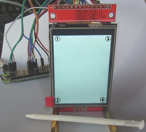
タッチパネル入力プログラム「touch-test.py」の実行時のLCDを次に示します。画面に付与した数値はタッチする場所を示します。タッチペンを使って、わりと強い力で画面を押します。
次の表は、LCDの場所ごとのタッチしたx,y位置を示します。
| 場所 | (x、y) |
|---|---|
| ① | (9、 308) |
| ➁ | (6、 6) |
| ③ | (218、 309) |
| ④ | (223、 7) |


