「プログラマブル波形発生器「AD9833」による三角波/サイン波の発生」で、Arduino Uno R3を使用しましたが、今回はESP8266上でプログラマブル波形発生器「AD9833」による波形を発生させます。
ESP8266とAD9833の接続
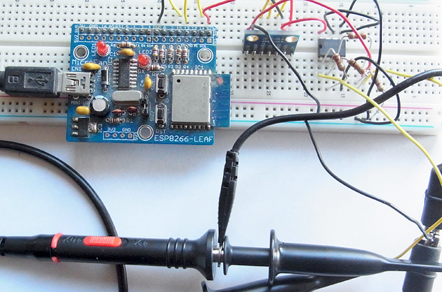
ESP8266とAD9833は、次のようにSPIインタフェースで接続して、AD9833の「OUT」、オペアンプの増幅後の出力にはオシロスコープを接続します。
| ESP8266 | AD9833 |
|---|---|
| 3.3V | Vcc |
| GND | DGND |
| SCK | SCLK |
| MOSI | SDATA |
| SS | FSYNC |
波形発生プログラムの作成
ESP8266のプログラムは、前回Arduino Uno R3で使用したプログラムに、次のようにな変更しています。
- 12行目でFSYNC信号を定義しなおしています。
- 25-27行目でFSYNC信号をHIGHにしています。
signalgen.ino
/*
AD9833 Waveform Module vwlowen.co.uk
*/

#include <SPI.h>

const int SINE = 0x2000;                    // Define AD9833's waveform register value.
const int SQUARE = 0x2028;                  // When we update the frequency, we need to
const int TRIANGLE = 0x2002;                // define the waveform when we end writing.
const float refFreq = 25000000.0;           // On-board crystal reference frequency
//const int FSYNC = 10;                       // Standard SPI pins for the AD9833 waveform generator.
const int FSYNC = SS;                       // Standard SPI pins for the AD9833 waveform generator.

int waveType = SQUARE;
unsigned long freq = 1000000;               // Set initial frequency.

void setup() {
  Serial.begin(9600);
  Serial.println("AD9833 Test");


  // Can't set SPI MODE here because the display and the AD9833 use different MODES.
  SPI.begin();

  // SSをHightに
  pinMode(FSYNC, OUTPUT);
  digitalWrite(FSYNC, HIGH);

  delay(50);
  AD9833reset();                                   // Reset AD9833 module after power-up.
  delay(50);
  AD9833setFrequency(freq, waveType);                  // Set the frequency and Sine Wave output
}

void loop() {
}

// AD9833 documentation advises a 'Reset' on first applying power.
void AD9833reset() {
  WriteRegister(0x100);   // Write '1' to AD9833 Control register bit D8.
  delay(10);
}

// Set the frequency and waveform registers in the AD9833.
void AD9833setFrequency(long frequency, int Waveform) {

  long FreqWord = (frequency * pow(2, 28)) / refFreq;

  int MSB = (int)((FreqWord & 0xFFFC000) >> 14);    //Only lower 14 bits are used for data
  int LSB = (int)(FreqWord & 0x3FFF);

  //Set control bits 15 ande 14 to 0 and 1, respectively, for frequency register 0
  LSB |= 0x4000;
  MSB |= 0x4000;

  WriteRegister(0x2100);
  WriteRegister(LSB);                  // Write lower 16 bits to AD9833 registers
  WriteRegister(MSB);                  // Write upper 16 bits to AD9833 registers.
  WriteRegister(0xC000);               // Phase register
  WriteRegister(Waveform);             // Exit & Reset to SINE, SQUARE or TRIANGLE

}

void WriteRegister(int dat) {

  // Display and AD9833 use different SPI MODES so it has to be set for the AD9833 here.
  SPI.setDataMode(SPI_MODE2);

  digitalWrite(FSYNC, LOW);           // Set FSYNC low before writing to AD9833 registers
  delayMicroseconds(10);              // Give AD9833 time to get ready to receive data.

  SPI.transfer(highByte(dat));        // Each AD9833 register is 32 bits wide and each 16
  SPI.transfer(lowByte(dat));         // bits has to be transferred as 2 x 8-bit bytes.

  digitalWrite(FSYNC, HIGH);          //Write done. Set FSYNC high
}
SPIインタフェースの信号波形の観測
SPIインタフェースの次のような信号波形をロジアナで観測しました。以降に赤数字で示すポイントの信号波形を示します。
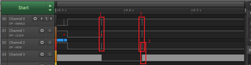
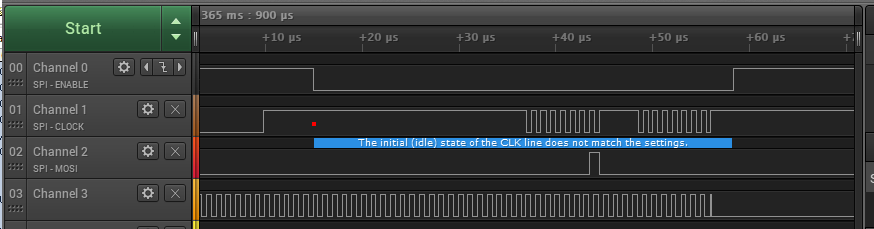
ポイント1の信号波形
ポイント1はreset信号を示し、関数「AD9833reset」で発生します。
ポイント2の信号波形
ポイント2は周波数と波形の設定信号を示し、関数「AD9833setFrequency」で発生します。
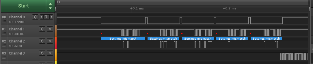
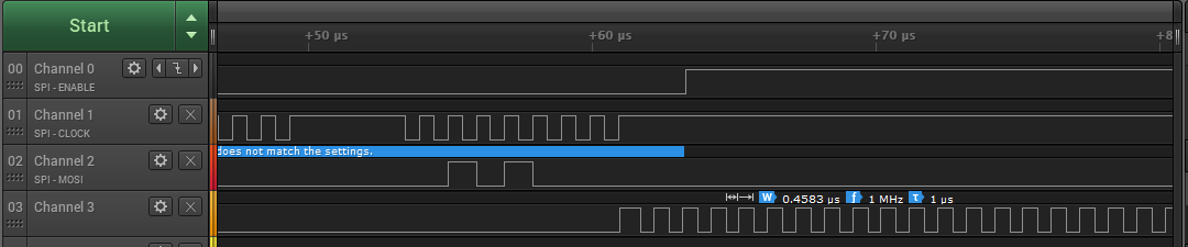
ポイント3の信号波形
ポイント3はAD9833が発生した1MHzの矩形波信号を示します。
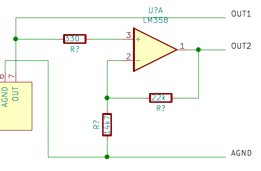
オペアンプによる発生信号の増幅
オペアンプ「LM358P」を使用して、次の回路により発生した信号を増幅します。なお、ピン8には「3.3V」、ピン4には「GND」を接続します。
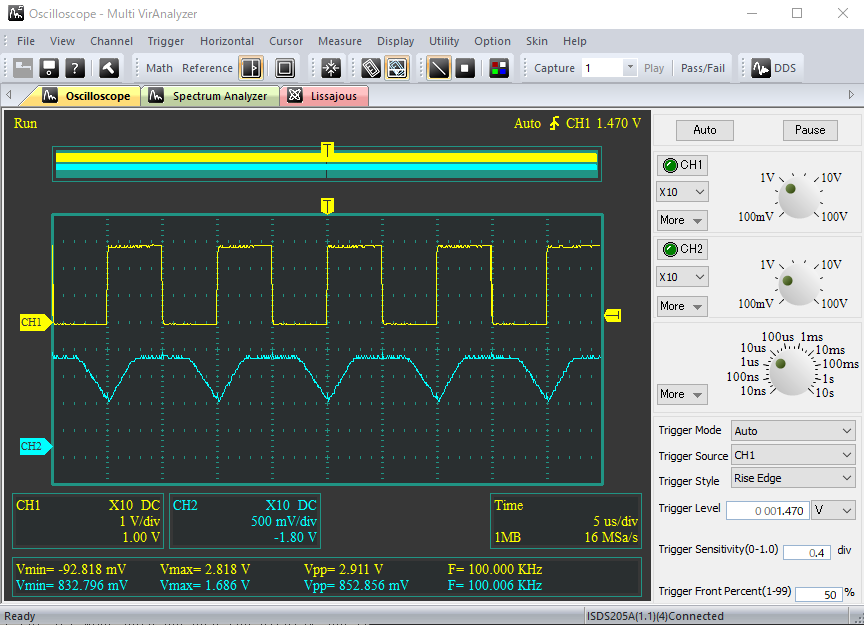
発生信号の観測
100kHzでそれぞれの波形を発生させました。CH1が上記の回路の「OUT1」、CH2が「OUT2」の位置での観測となります。
サイン波

<
三角波
a href=”https://tomosoft.jp/design/wp-content/uploads/2020/12/spi05.png”>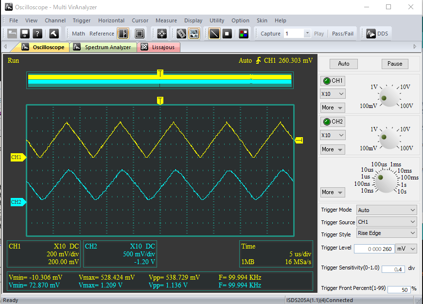
矩形波
オペアンプによる増幅では波形が崩れてしまいました。高速のオペアンプが必要です。