
メカトラックス株式会社様からラズパイIoTスタータキット「anyPi(エニーパイ)」とGPSアンテナ(オプション品)を提供していただいたので、さっそく同梱されているPiConsole I/Fの入出力を動作させてみました。PiConsole I/Fは、次の部品が実装されており、今回は確認しませんが、USB(mini USB)シリアル変換インターフェースも実装されており、パソコンとの通信も可能です。
- テキスト表示ディスプレイ(LCD)(16文字2行)
- LED(赤・黄)
- タクトスイッチ(SW)(白・黒)
- 電子ブザー
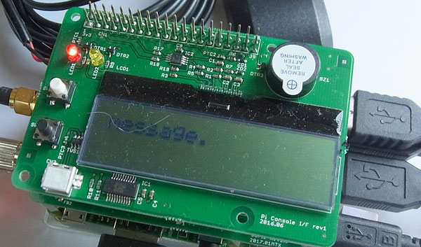
anyPiのPiConsole I/Fの画像を次に示します。各サンプルプログラムを実行した状態でキャプチャしました。
PiConsole I/Fのインタフェース仕様
それぞれのGPIO番号を次に示します。なおテキスト表示ディスプレイは、AQM1602XAで、コントロールICに「ST7032i」を使用し、I2Cでインタフェースされます。
| GPIO名 | PIN番号 | 設定 | 機能 |
|---|---|---|---|
| GPIO20 | 38 | 出力 | LED1(赤) |
| GPIO21 | 40 | 出力 | LED2(黄) |
| GPIO25 | 22 | 出力 | 電子ブザー |
| GPIO19 | 35 | 入力 | SW1(白) |
| GPIO16 | 36 | 入力 | SW2(黒) |
| GPIO2 | 3 | 入出力 | LCD(SDA) |
| GPIO3 | 5 | 入出力 | LCD(SCL) |
| GPIO14 | 8 | 入出力 | シリアル変換インターフェース(TXD) |
| GPIO15 | 10 | 入出力 | シリアル変換インターフェース(RXD) |
PiConsole I/Fのサンプルプログラム
PiConsole I/FのサンプルプログラムをPython言語と、同梱されているRaspbian Jessieにもすでにインストールされているpigpioを使用して作成します。
動作環境の設定
次の手順に従って、pigpiodやI2Cのインタフェースを設定します。
- pigpiodやI2Cのインタフェースをディスクトップ画面からイネーブルにします。
タスクバー上から「apprications menu」 → 「Preferences」 → 「Raspberry Pi Configuration」を選択して、表示されたダイアログの「Interfaces」をクリックする。表示されたインタフェースのI2C Remote GPIOを「Enabled」に設定する。 - 次のようにpigpioのサービスを有効化します。
- 起動時から有効にしたい場合は次のコマンドを入力します。
$ sudo pigpiod
$ sudo systemctl enable pigpiod.service
$ sudo systemctl restart pigpiod.service
<注意>
プログラムを実行すると、次のエラーメッセージを表示する場合があります。この場合、pigpiodの実行環境が正しく設定されていないので、上記の動作環境をもう一度確認してください。
pi@raspberrypi:~/pythonalps $ python lcd.py
%%%%%%%%%%%%%%%%%%%%%%%%%%%%%%%%%%%%%%%%%%%%%%%%%%%%%%%%%%%%
Can't connect to pigpio at localhost(8888)

Did you start the pigpio daemon? E.g. sudo pigpiod

Did you specify the correct Pi host/port in the environment
variables PIGPIO_ADDR/PIGPIO_PORT?
E.g. export PIGPIO_ADDR=soft, export PIGPIO_PORT=8888

Did you specify the correct Pi host/port in the
pigpio.pi() function? E.g. pigpio.pi('soft', 8888))
%%%%%%%%%%%%%%%%%%%%%%%%%%%%%%%%%%%%%%%%%%%%%%%%%%%%%%%%%%%%
LED,SW,電子ブザー用サンプルプログラム
LED,SW,電子ブザー用サンプルプログラムを実行すると、PiConsole I/FのLED,SW,電子ブザーが次のように動作します。
- SW(白)を押すごとに、LEDが点灯/消灯を繰り返します。
- SW(白)を押すごとに、電子ブザーの音が変化します。
#!/usr/bin/env python
# -*- coding: utf-8 -*-

import pigpio
from time import sleep

# -----------
callcnt = 0
Buzzer = 25	#ブザー
LED = 20	#赤
SW = 19		#白
FREQ = 50
RANGE = 100

pi = pigpio.pi()
pi.set_mode(SW, pigpio.INPUT)
pi.set_pull_up_down(SW, pigpio.PUD_UP)
pi.set_mode(LED, pigpio.OUTPUT)


def cb_interrupt(gpio, level, tick):
    global callcnt
    print (gpio, level, tick)
    callcnt += 1
    pi.write(LED,callcnt & 1)
    pi.set_PWM_frequency(Buzzer, FREQ)
    pi.set_PWM_range(Buzzer, RANGE)
    pi.set_PWM_dutycycle(Buzzer, callcnt*1)

cb = pi.callback(SW, pigpio.FALLING_EDGE, cb_interrupt)

pi = pigpio.pi()
pi.set_mode(Buzzer, pigpio.OUTPUT)

try:
    while True:
        pi.write(Buzzer, 1)
        sleep(0.5)
        pi.write(Buzzer, 0)
        sleep(0.5)
        if callcnt != 0:
            while True:
                sleep(0.5)

except KeyboardInterrupt:
    pass

pi.set_mode(Buzzer, pigpio.INPUT)
pi.stop()
LCD用サンプルプログラム
LCD用サンプルプログラムを実行すると、次のようにLCDに表示されます。なおこのサンプルプログラムは「WiringPi-Pythonを使ってAQM0802A / ST7032i LCD表示」をベースにして、pigpioで動作するように変更しました。
- 1行目1カラムから「1234」、2行目5カラムから「5678」を表示します
- 1行目8カラムにtickerにより「Hello, this is a ticker message.」を表示します
#!/usr/bin/env python3
# -*- coding:utf-8 -*-

"""
ST7032i LCD driver control library
"""

import pigpio
import time

I2C_ADDR = 0x3e

class St7032iLCD:
    """
    ST7032i LCD control class
    """
    def __init__(self, i2c_addr = I2C_ADDR):
        self.pi = pigpio.pi()
        if not self.pi.connected:
           exit(0)
        self._h = self.pi.i2c_open(1, i2c_addr)

        self._init()

    def _init(self):
        self._inst(0x38) # function set: 8 bit, 2 line
        self._inst(0x39) # function set: 8 bit, 2 line, IS=1
        self._inst(0x14) # internal OSC freq
        self._inst(0x70) # contrast set
        self._inst(0x56) # Power/ICON/Constrast
        self._inst(0x6c) # Follower control
        time.sleep(0.2)  # wait time > 200 ms
        self._inst(0x38) # function set: 8 bit, 2 line, IS=0
        self._inst(0x06) # Entry mode set
        self._inst(0x0c) # Display on/off
        self._inst(0x01) # Clear display
        time.sleep(0.01) # wait time > 1.08 ms
        self._inst(0x02) # return home
        time.sleep(0.01) # wait time > 1.08 ms

    def _write(self, control, data):
         self.pi.i2c_write_byte_data(self._h, control, data)

    def _inst(self, data):
        """ Send Instruction code. """
        self._write(0x00, data)

    def write_data(self, data):
        """ Send data into data register. """
        self._write(0x40, data)

    def clear(self):
        """ Clear display and return to home position. """
        self._inst(0x01) # clear display
        time.sleep(0.01) # wait time > 1.08 ms
        self._inst(0x02) # return home
        time.sleep(0.01) # wait time > 1.08 ms

    def return_home(self):
        """ return to home """
        self._inst(0x02) # return home
        time.sleep(0.01)             # wait time > 1.08 ms

    def set_contrast(self, contrast):
        """ Set contrast (0 - 15). """
        if contrast < 0:
            contrast = 0
        if contrast > 0x0f:
            contrast = 0x0f
        self._inst(0x39)
        self._inst(0x70 + contrast)

    def set_cursor(self, x, y):
        """ set cursor location (address counter)."""
        if x < 0: x = 0
        if y < 0: y = 0
        ddram_addr = y * 0x40 + x
        self._inst(0x80 + ddram_addr) # set DDRAM address

    def set_entry_mode(self, increment, shift):
        mode = 0x04
        if (increment): mode = mode + 2
        if (shift): mode = mode + 1
        self._inst(mode)

    def put_line(self, str, wait = 0):
        for c in str:
            self.write_data(ord(c))
            if (wait > 0): time.sleep(wait)

if __name__ == '__main__':
    lcd = St7032iLCD(I2C_ADDR)

    # show characters in 2 lines
    lcd.set_cursor(0, 0)
    lcd.put_line('1234')
    lcd.set_cursor(4, 1)
    lcd.put_line('5678')

    # LCD clear
    time.sleep(2)
    lcd.clear()

    # ticker
    lcd.set_entry_mode(True, True)
    lcd.set_cursor(8, 0)
    lcd.put_line('Hello, this is a ticker message.', 0.5)