
ebayで購入したPro Micro にデジタルコンパス・加速度センサ「LSM303DLH」を接続し、デジタルコンパス・加速度を入力プログラムを作成しました。LSM303DLHは、スイッチサイエンスや秋月電子などが販売されていますが、今回はebeyから購入しました。次に、購入したデジタルコンパス・加速度センサ「LSM303DLH」を示します。
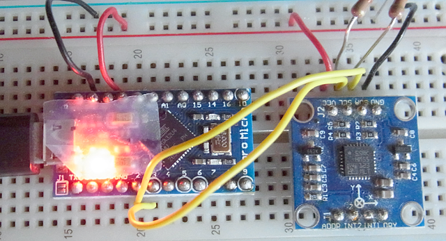
Pro Microとデジタルコンパス・加速度センサ「LSM303DLH」の接続
Pro Microとデジタルコンパス・加速度センサ「LSM303DLH」間は、I2Cインタフェースで接続します。次のように各ピンを接続します。左側のピン番号がLSM303DLHで右側のピン番号がPro Microです。
- VCC(3~5V) -> VCC
- GND -> GND
- SDA -> D2
- SCL -> D3
- SDA,SCLを10kΩでプルアップ
Arduinoの標準では信号線はプルアップは行われていますが、ProMicroのI2Cの信号線はプルアップされていません。
「Pro MicroによるOLEDディスプレイ への表示」で作成したi2c_scanner1によりI2 Cのアドレスを確認します。
I2C Scanner
     0  1  2  3  4  5  6  7  8  9  A  B  C  D  E  F
00: xx xx xx xx xx xx xx xx -- -- -- -- -- -- -- --
10: -- -- -- -- -- -- -- -- 18 -- -- -- -- -- 1E --
20: -- -- -- -- -- -- -- -- -- -- -- -- -- -- -- --
30: -- -- -- -- -- -- -- -- -- -- -- -- -- -- -- --
40: -- -- -- -- -- -- -- -- -- -- -- -- -- -- -- --
50: -- -- -- -- -- -- -- -- -- -- -- -- -- -- -- --
60: -- -- -- -- -- -- -- -- -- -- -- -- -- -- -- --
70: -- -- -- -- -- -- -- -- xx xx xx xx xx xx xx xx
I2Cアドレスは、「0x18」が加速度センサー、「0x1e 」がデジタルコンパスになっていました。
LSM303DLHによるデジタルコンパス・加速度プログラムの作成
LSM303DLHによるデジタルコンパス・加速度プログラムを次に示します。LSM303DLHのライブラリは「Arduino library for Pololu LSM303 boards」で提供されていますが、今回はArduinoのI2Cライブラリ「Wire」を使って、LSM303DLHのレジスタに設定していきます。
- 50行目から55行目で加速度加速度センサーからのデータを取得します。データは12ビット長でリトルエンディアンで設定されています。
- 61行目から66行目でデジタルコンパスからのデータを取得します。データは16ビット長でビッグエンディアンで設定されています。z軸のデータは、y軸のデータの前に取得します
Serial.ino
#include <Wire.h>

#define SDA  4
#define SCL  5

int  compass_a_x, compass_a_y, compass_a_z;
int  compass_m_x, compass_m_y, compass_m_z;

char report[80];

void setup()
{
  Serial.begin(9600);
  while ( !Serial ) {
  }

  Wire.begin();
  compass_init();
}

void loop()
{
  compass_read();

  snprintf(report, sizeof(report), "A: %6d %6d %6d    M: %6d %6d %6d",
           compass_a_x, compass_a_y, compass_a_z,
           compass_m_x, compass_m_y, compass_m_z);
  Serial.println(report);

  delay(1000);
}

void  compass_init() {
  Wire.beginTransmission(0x18);
  Wire.write(0x20);
  Wire.write(0x27);
  Wire.endTransmission();

  Wire.beginTransmission(0x1E);
  Wire.write(0x02);
  Wire.write(0x00);
  Wire.endTransmission();
}

void  compass_read() {
  Wire.beginTransmission(0x18);
  Wire.write(0x28 | 0x80);
  Wire.endTransmission();
  Wire.requestFrom(0x18, 6);
  byte b = Wire.read();
  compass_a_x = (int16_t)(Wire.read() << 8 | b);
  b = Wire.read();
  compass_a_y = (int16_t)(Wire.read() << 8 | b);
  b = Wire.read();
  compass_a_z = (int16_t)(Wire.read() << 8 | b);

  Wire.beginTransmission(0x1e);
  Wire.write(0x03);
  Wire.endTransmission();
  Wire.requestFrom(0x1e, 6);
  b = Wire.read();
  compass_m_x = (int16_t)(b << 8 | Wire.read());
  b = Wire.read();
  compass_m_z = (int16_t)(b << 8 | Wire.read());
  b = Wire.read();
  compass_m_y = (int16_t)(b << 8 | Wire.read());

}
LSM303DLHによるデジタルコンパス・加速度プログラムの実行
作成したデジタルコンパス・加速度プログラム「Serial.ino」をPro Microに書き込み、実行すると、パソコン上で実行しているTeratermには、次のような加速度センサX/Y/Z、デジタルコンパスX/Y/Zの値(計6軸)のデータが表示されます。
A:   -304    128     -1    M:     -1     -1     -1
A:   -464    128  16448    M:   -119    -35   -405
A:   -400    160  16400    M:   -114    -32   -404
A:   -352    224  16416    M:   -113    -29   -397
A:   -384    144  16400    M:   -115    -39   -399
A:   -384    192  16400    M:   -116    -33   -399
A:   -400    176  16448    M:   -115    -40   -399
A:   -352    128  16448    M:   -117    -27   -396
A:   -384    208  16448    M:   -114    -33   -404
A:   -352    128  16384    M:   -117    -35   -400
A:   -400    192  16448    M:   -120    -30   -399
A:   -288    192  16336    M:   -112    -30   -388
A:   -384    160  16480    M:   -121    -35   -398
A:   -400    128  16368    M:   -114    -40   -400
A:   -400    240  16304    M:   -139    -29   -393
A:   -432     48  16336    M:   -180    -29   -374
A:   -352     80  16464    M:   -199    -26   -361
A:   -400    208  16464    M:   -210    -29   -350
A:   -496    128  16448    M:   -229    -31   -339
A:   -384    160  16464    M:   -253    -26   -318
A:   -336    288  16464    M:   -255    -32   -323