
前回AT90USB162を作成しましたが、これを使ってCDCデバイスを開発しました。
CDCデバイスは、USBインタフェースの一つであるCDCクラス(Communication Device Class)を使用し、パソコン側のアプリケーション・プログラムは、シリアルインタフェースで通信できます。ちなみに、他のUSBインタフェースのクラスととして、主にキーボードやマウスに使用されるHIDや、接続されたUSB機器を記憶装置として認識し制御するMSCがあり、PC側に専用のドライバは特に必要としません。
今回は、Atmel Studio 6.2にLUFAをインストールし、LUFAで提供されている「USB to Serial Converter – AVR8Architecture」をAT90USB162に書き込み、CDCデバイスとして作成したAT90USB162をパソコンと接続して、パソコンのCOMポートで接続したAT90USB162と通信できることを確認します。
開発環境
Atmel Studio 6.2
Flip 3.4.7
LUFA 14.9.28.140928
Windows 7 Professional
Atmel Studio 6.2へLUFAのインストール
Atmel Studio 6.2は、インストール時にはLUFAをインストールしていないため、次の手順でLUFAをインストールします。最初にAtmel Studioを起動するすると、次に示すAtmel Galleryから更新のダイアログが表示されます。
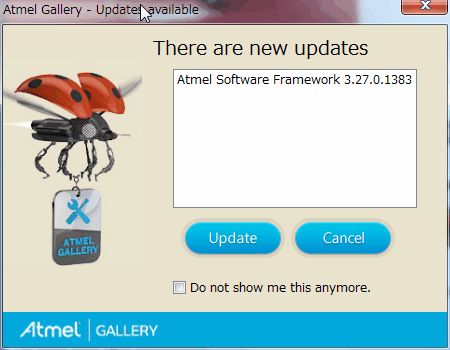
Updateボタンを押すと、次に示すLUFA Libraryのインストールダイアログが表示されるので、選択してクリックするとAtmel StudioにLUFAがインストールされます。
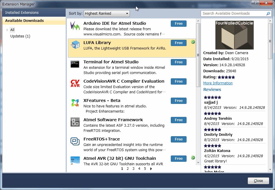
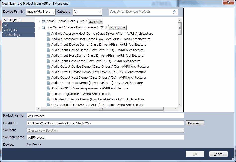
Atmel StudioにLUFAをインストール完了後、メニューから、「New」「Project Example…」を選択すると、次のLUFA Extensionsダイアログに「FourWalledCubicle – Dean Camera」が表示され、LUFAがインストールされていることが確認できます。
LUFAのCDCコードの取得・ビルド
LUFAから提供されるCDCコード「USB to Serial Converter – AVR8Architecture」のビルドを行い、FlipによりAT90USB162に書き込むためのHEXファイルを作成します。
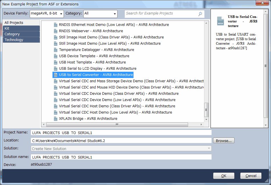
メニューから、「New」「Project Example…」を選択すると、次のLUFA Extensionsダイアログに「FourWalledCubicle – Dean Camera」に「USB to Serial Converter – AVR8Architecture」が表示されるので選択します。
Atmel Studio画面が次のように表示されます。
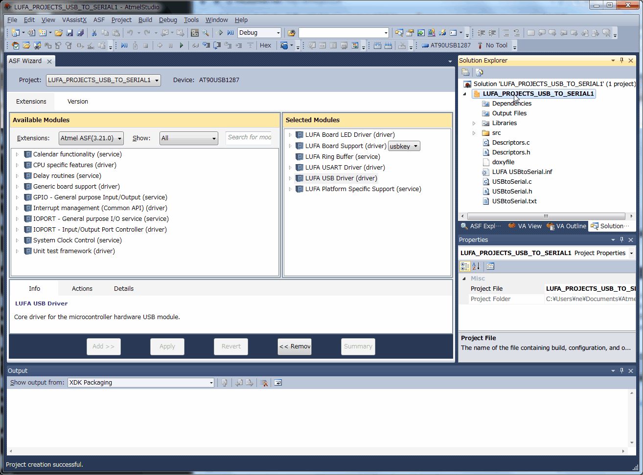
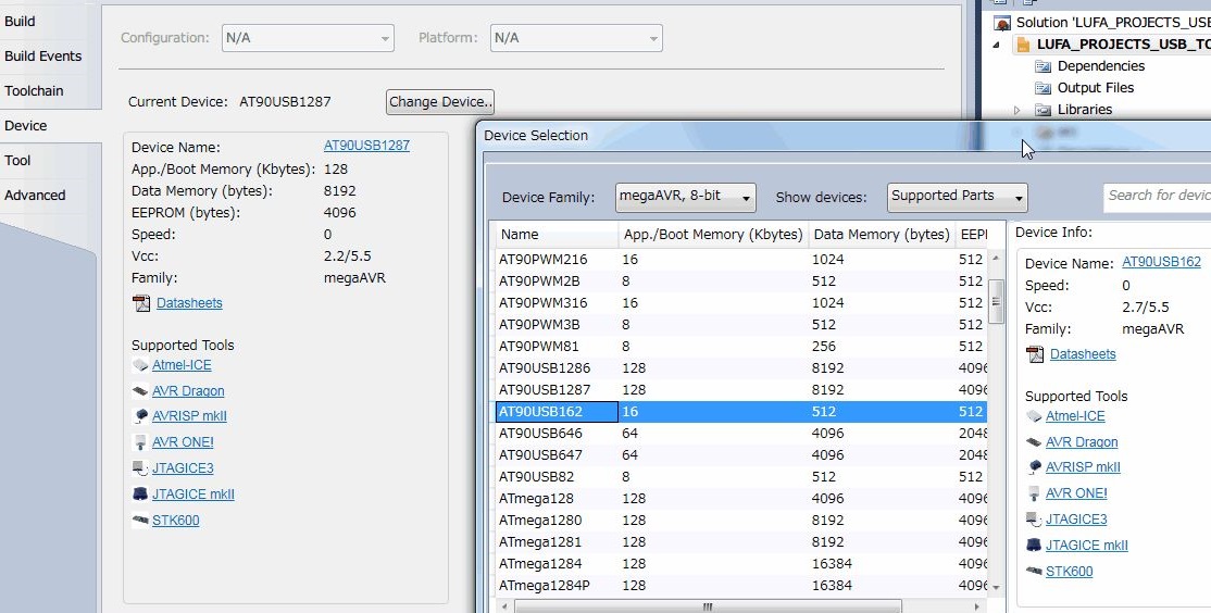
サンプルプロジェクトのプロパティを見ますと AT90USB1287 を使用するようになっています。今回使うのは AT90USB162 なので 、次のダイアログを使用して、[Change Deivce] ボタンを押して AT90USB162 に修正します。
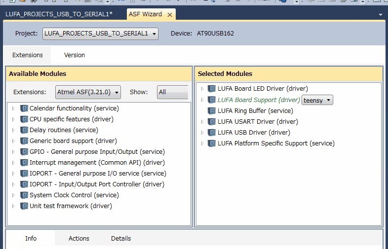
サンプルプロジェクトは、AT90USBKEY というボードを使用するようになっているため、[ASF] -> [ASF Wizard] を起動し、次のダイアログを表示させます。ここで右側ペインの中にあるリストボックスが USBKEY になっているのを、AT90USB162の回路のベースになった「teensy」に変更します。
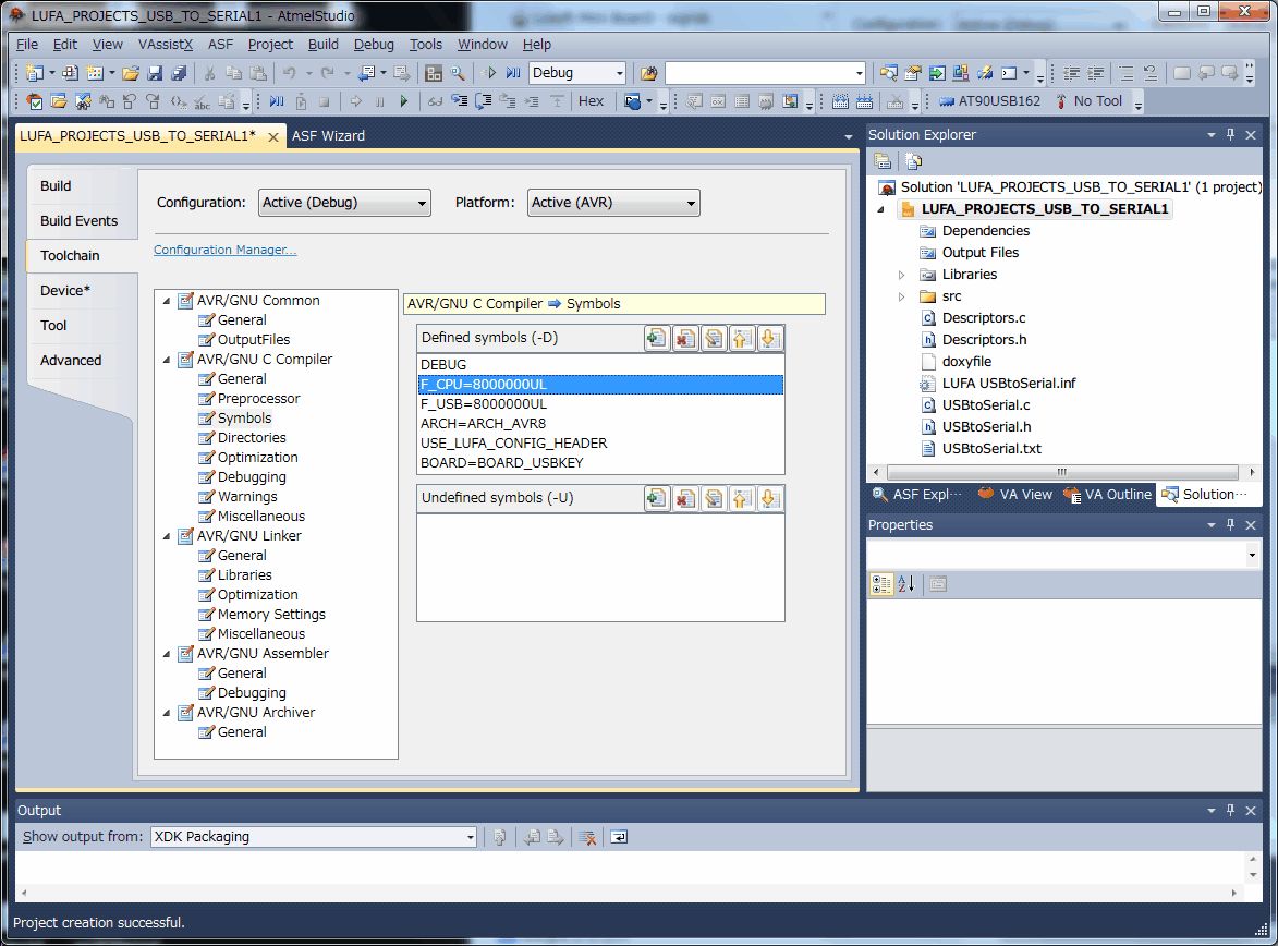
次はプロジェクトをビルドする時の指定をプロパティのToolchainを用いて次のように変更します。「F_CPU=8000000UL 」と「 F_USB=8000000UL」 は 8MHz クロックの指定のため、 16MHz なので「 16000000UL」 に修正 します。
次に、Atmel Studio画面のメニューの「Build」「Rebuild Solution」を選択してCDCデバイスのソースコードをコンパイルして、Hexファイルを作成する。
Flipを使用したAT90USB162へCDCコードの書き込み
Flipを使用したAT90USB162へCDCコードの書き込み方法は、「Atmel Studioで開発したAT90USB162のLED点灯プログラム作成」 を参照してください。ただし、書き込むHexファイルをDebugフォルダのCDCデバイスプログラム「LUFA_PROJECTS_USB_TO_SERIAL1.hex」ファイルを選択します。
パソコンとAT90USB162のシリアル通信
パソコンにAT90USB162を接続し、デバイスマネージャを表示すると、シリアルポート「LUFA USB to Serial(COMnn)」 が表示されます。実際のシリアルデータ転送を確認するために、AT90USB162 の TXD/RXD をそのまま接続してループバックさせ、Teratermによりパソコンからシリアルデータを転送して、エコーバックによりTeratermの画面に表示されることを確認しまた。
参考ソースコード
CDCデバイスのソースコード(mainの部分)を次に示します。
USBtoSerial.c
/*
             LUFA Library
     Copyright (C) Dean Camera, 2014.

  dean [at] fourwalledcubicle [dot] com
           www.lufa-lib.org
*/

/*
  Copyright 2014  Dean Camera (dean [at] fourwalledcubicle [dot] com)

  Permission to use, copy, modify, distribute, and sell this
  software and its documentation for any purpose is hereby granted
  without fee, provided that the above copyright notice appear in
  all copies and that both that the copyright notice and this
  permission notice and warranty disclaimer appear in supporting
  documentation, and that the name of the author not be used in
  advertising or publicity pertaining to distribution of the
  software without specific, written prior permission.

  The author disclaims all warranties with regard to this
  software, including all implied warranties of merchantability
  and fitness.  In no event shall the author be liable for any
  special, indirect or consequential damages or any damages
  whatsoever resulting from loss of use, data or profits, whether
  in an action of contract, negligence or other tortious action,
  arising out of or in connection with the use or performance of
  this software.
*/

/** \file
 *
 *  Main source file for the USBtoSerial project. This file contains the main tasks of
 *  the project and is responsible for the initial application hardware configuration.
 */

#include "USBtoSerial.h"

/** Circular buffer to hold data from the host before it is sent to the device via the serial port. */
static RingBuffer_t USBtoUSART_Buffer;

/** Underlying data buffer for \ref USBtoUSART_Buffer, where the stored bytes are located. */
static uint8_t      USBtoUSART_Buffer_Data[128];

/** Circular buffer to hold data from the serial port before it is sent to the host. */
static RingBuffer_t USARTtoUSB_Buffer;

/** Underlying data buffer for \ref USARTtoUSB_Buffer, where the stored bytes are located. */
static uint8_t      USARTtoUSB_Buffer_Data[128];

/** LUFA CDC Class driver interface configuration and state information. This structure is
 *  passed to all CDC Class driver functions, so that multiple instances of the same class
 *  within a device can be differentiated from one another.
 */
USB_ClassInfo_CDC_Device_t VirtualSerial_CDC_Interface =
	{
		.Config =
			{
				.ControlInterfaceNumber         = INTERFACE_ID_CDC_CCI,
				.DataINEndpoint                 =
					{
						.Address                = CDC_TX_EPADDR,
						.Size                   = CDC_TXRX_EPSIZE,
						.Banks                  = 1,
					},
				.DataOUTEndpoint                =
					{
						.Address                = CDC_RX_EPADDR,
						.Size                   = CDC_TXRX_EPSIZE,
						.Banks                  = 1,
					},
				.NotificationEndpoint           =
					{
						.Address                = CDC_NOTIFICATION_EPADDR,
						.Size                   = CDC_NOTIFICATION_EPSIZE,
						.Banks                  = 1,
					},
			},
	};


/** Main program entry point. This routine contains the overall program flow, including initial
 *  setup of all components and the main program loop.
 */
int main(void)
{
	SetupHardware();

	RingBuffer_InitBuffer(&USBtoUSART_Buffer, USBtoUSART_Buffer_Data, sizeof(USBtoUSART_Buffer_Data));
	RingBuffer_InitBuffer(&USARTtoUSB_Buffer, USARTtoUSB_Buffer_Data, sizeof(USARTtoUSB_Buffer_Data));

	LEDs_SetAllLEDs(LEDMASK_USB_NOTREADY);
	GlobalInterruptEnable();

	for (;;)
	{
		/* Only try to read in bytes from the CDC interface if the transmit buffer is not full */
		if (!(RingBuffer_IsFull(&USBtoUSART_Buffer)))
		{
			int16_t ReceivedByte = CDC_Device_ReceiveByte(&VirtualSerial_CDC_Interface);

			/* Store received byte into the USART transmit buffer */
			if (!(ReceivedByte < 0))
			  RingBuffer_Insert(&USBtoUSART_Buffer, ReceivedByte);
		}

		uint16_t BufferCount = RingBuffer_GetCount(&USARTtoUSB_Buffer);
		if (BufferCount)
		{
			Endpoint_SelectEndpoint(VirtualSerial_CDC_Interface.Config.DataINEndpoint.Address);

			/* Check if a packet is already enqueued to the host - if so, we shouldn't try to send more data
			 * until it completes as there is a chance nothing is listening and a lengthy timeout could occur */
			if (Endpoint_IsINReady())
			{
				/* Never send more than one bank size less one byte to the host at a time, so that we don't block
				 * while a Zero Length Packet (ZLP) to terminate the transfer is sent if the host isn't listening */
				uint8_t BytesToSend = MIN(BufferCount, (CDC_TXRX_EPSIZE - 1));

				/* Read bytes from the USART receive buffer into the USB IN endpoint */
				while (BytesToSend--)
				{
					/* Try to send the next byte of data to the host, abort if there is an error without dequeuing */
					if (CDC_Device_SendByte(&VirtualSerial_CDC_Interface,
											RingBuffer_Peek(&USARTtoUSB_Buffer)) != ENDPOINT_READYWAIT_NoError)
					{
						break;
					}

					/* Dequeue the already sent byte from the buffer now we have confirmed that no transmission error occurred */
					RingBuffer_Remove(&USARTtoUSB_Buffer);
				}
			}
		}

		/* Load the next byte from the USART transmit buffer into the USART if transmit buffer space is available */
		if (Serial_IsSendReady() && !(RingBuffer_IsEmpty(&USBtoUSART_Buffer)))
		  Serial_SendByte(RingBuffer_Remove(&USBtoUSART_Buffer));

		CDC_Device_USBTask(&VirtualSerial_CDC_Interface);
		USB_USBTask();
	}
}

/** Configures the board hardware and chip peripherals for the demo's functionality. */
void SetupHardware(void)
{
#if (ARCH == ARCH_AVR8)
	/* Disable watchdog if enabled by bootloader/fuses */
	MCUSR &= ~(1 << WDRF);
	wdt_disable();

	/* Disable clock division */
	clock_prescale_set(clock_div_1);
#endif

	/* Hardware Initialization */
	LEDs_Init();
	USB_Init();
}

/** Event handler for the library USB Connection event. */
void EVENT_USB_Device_Connect(void)
{
	LEDs_SetAllLEDs(LEDMASK_USB_ENUMERATING);
}

/** Event handler for the library USB Disconnection event. */
void EVENT_USB_Device_Disconnect(void)
{
	LEDs_SetAllLEDs(LEDMASK_USB_NOTREADY);
}

/** Event handler for the library USB Configuration Changed event. */
void EVENT_USB_Device_ConfigurationChanged(void)
{
	bool ConfigSuccess = true;

	ConfigSuccess &= CDC_Device_ConfigureEndpoints(&VirtualSerial_CDC_Interface);

	LEDs_SetAllLEDs(ConfigSuccess ? LEDMASK_USB_READY : LEDMASK_USB_ERROR);
}

/** Event handler for the library USB Control Request reception event. */
void EVENT_USB_Device_ControlRequest(void)
{
	CDC_Device_ProcessControlRequest(&VirtualSerial_CDC_Interface);
}

/** ISR to manage the reception of data from the serial port, placing received bytes into a circular buffer
 *  for later transmission to the host.
 */
ISR(USART1_RX_vect, ISR_BLOCK)
{
	uint8_t ReceivedByte = UDR1;

	if ((USB_DeviceState == DEVICE_STATE_Configured) && !(RingBuffer_IsFull(&USARTtoUSB_Buffer)))
	  RingBuffer_Insert(&USARTtoUSB_Buffer, ReceivedByte);
}

/** Event handler for the CDC Class driver Line Encoding Changed event.
 *
 *  \param[in] CDCInterfaceInfo  Pointer to the CDC class interface configuration structure being referenced
 */
void EVENT_CDC_Device_LineEncodingChanged(USB_ClassInfo_CDC_Device_t* const CDCInterfaceInfo)
{
	uint8_t ConfigMask = 0;

	switch (CDCInterfaceInfo->State.LineEncoding.ParityType)
	{
		case CDC_PARITY_Odd:
			ConfigMask = ((1 << UPM11) | (1 << UPM10));
			break;
		case CDC_PARITY_Even:
			ConfigMask = (1 << UPM11);
			break;
	}

	if (CDCInterfaceInfo->State.LineEncoding.CharFormat == CDC_LINEENCODING_TwoStopBits)
	  ConfigMask |= (1 << USBS1);

	switch (CDCInterfaceInfo->State.LineEncoding.DataBits)
	{
		case 6:
			ConfigMask |= (1 << UCSZ10);
			break;
		case 7:
			ConfigMask |= (1 << UCSZ11);
			break;
		case 8:
			ConfigMask |= ((1 << UCSZ11) | (1 << UCSZ10));
			break;
	}

	/* Keep the TX line held high (idle) while the USART is reconfigured */
	PORTD |= (1 << 3);

	/* Must turn off USART before reconfiguring it, otherwise incorrect operation may occur */
	UCSR1B = 0;
	UCSR1A = 0;
	UCSR1C = 0;

	/* Set the new baud rate before configuring the USART */
	UBRR1  = SERIAL_2X_UBBRVAL(CDCInterfaceInfo->State.LineEncoding.BaudRateBPS);

	/* Reconfigure the USART in double speed mode for a wider baud rate range at the expense of accuracy */
	UCSR1C = ConfigMask;
	UCSR1A = (1 << U2X1);
	UCSR1B = ((1 << RXCIE1) | (1 << TXEN1) | (1 << RXEN1));

	/* Release the TX line after the USART has been reconfigured */
	PORTD &= ~(1 << 3);
}