
Raspberry Pi 3にGPIOエキスパンダ「MCP23017」と「PC8574」を接続し、LEDを点滅させてタクトスイッチから入力して表示します。プログラム言語はPython3でライブラリ「pigpio」を使用します。Raspberry Pi 3の設定については「pigpioによるI2CとSPIインタフェースの実装」を参考にしてください。
GPIOエキスパンダ「MCP23017」の接続
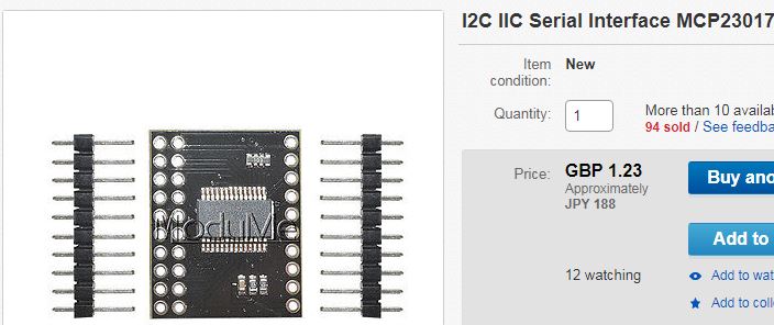
GPIOエキスパンダ「MCP23017」は、ebayから購入しました。GPIOエキスパンダ「MCP23017」は、16チャンネルありそれぞれのピンを入力/出力に割り付ける事が可能で、2ピンの割り込み入力とプルアップもでき、I2Cでインタフェースします。
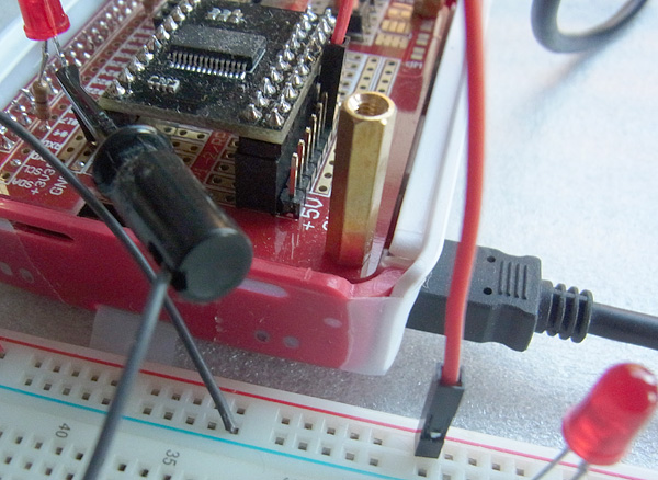
Raspberry Pi 3とGPIOエキスパンダ「MCP23017」間で、I2CのSDAとSCLのそれぞれに接続します。GPIOエキスパンダ「MCP23017」のVCCにはRaspberry Piの3.3Vを入力します。接続した図を次に示します。
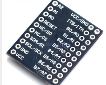
GPIOエキスパンダ「MCP23017」のピン配置を次に示します。
次のコマンドでRaspberry Pi 3との接続を確認します。
$ i2cdetect -y 1
     0  1  2  3  4  5  6  7  8  9  a  b  c  d  e  f
00:          -- -- -- -- -- -- -- -- -- -- -- -- --
10: -- -- -- -- -- -- -- -- -- -- -- -- -- -- -- --
20: 20 -- -- -- -- -- -- -- -- -- -- -- -- -- -- --
30: -- -- -- -- -- -- -- -- -- -- -- -- -- -- -- --
40: -- -- -- -- -- -- -- -- -- -- -- -- -- -- -- --
50: -- -- -- -- -- -- -- -- -- -- -- -- -- -- -- --
60: -- -- -- -- -- -- -- -- -- -- -- -- -- -- -- --
70: -- -- -- -- -- -- -- --
- GPIOエキスパンダ「MCP23017」のアドレス – 0×20
GPIOエキスパンダ「MCP23017」のPythonスクリプト
Python3でライブラリ「pigpio」を使用して、GPIOエキスパンダ「MCP23017」のPythonスクリプト「mMCP23017.py」を作成します。MCP23017のデータシートを示します。
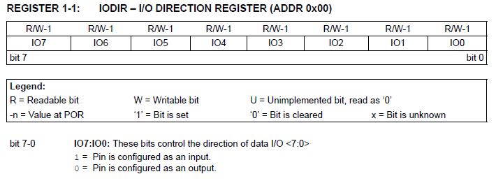
GPIOエキスパンダ「MCP23017」のレジスタの一覧を次に示します。
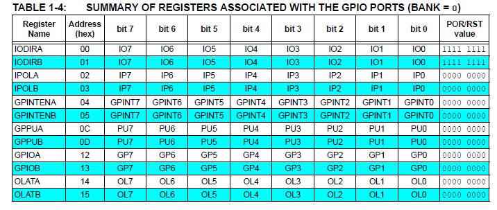
I/O方向レジスタの形式を次に示します。GPA0(21) 〜 GPA7(28)の出入力設定を行います。
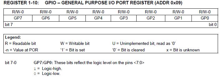
I/Oポートレジスタの形式を次に示します。
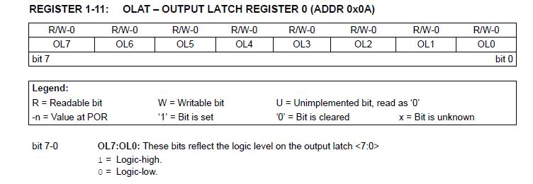
出力ラッチレジスタの形式を次に示します。GPA0(21) 〜 GPA7(28)の出力制御(出力オン/オフ)を行います。
mMCP23017.py
import time
import mMCP23017
import pigpio

class MCP23017(object):
    DEFAULT_ADDRESS  = 0x20

    REG_IODIRA = 0x00   # 入出力設定レジスタA
    REG_IODIRB = 0x01   # 入出力設定レジスタB
    REG_GPIOA  = 0x12   # 入力レジスタB
    REG_GPIOB  = 0x13   # 入力レジスタB
    REG_OLATA  = 0x14   # 出力レジスタA

    def __init__(self, pi):
        self.pi = pi
        self._device = pi.i2c_open(1, self.DEFAULT_ADDRESS)

    def output(self):
        reg_data = [self.REG_IODIRA, 0]
        self.pi.i2c_write_device(self._device, reg_data)

        time.sleep(2)
        reg_data = [self.REG_OLATA, 0x10]
        self.pi.i2c_write_device(self._device, reg_data)
        time.sleep(2)
        reg_data = [self.REG_OLATA, 0x0]
        self.pi.i2c_write_device(self._device, reg_data)

    def input(self):
        reg_data = [self.REG_IODIRB, 0xff]
#         reg_data = [self.REG_IODIRA, 0xff]
        self.pi.i2c_write_device(self._device, reg_data)

        reg_data = self.REG_GPIOB
#         reg_data = self.REG_GPIOA
        wc,data =  self.pi.i2c_read_i2c_block_data(self._device, reg_data,2)
        print("input:{:x}".format(data[0]))
        time.sleep(2)

    def cancel(self):
        if self._device is not None:
            self.pi.i2c_close(self._device)
            self._device = None


if __name__ == "__main__":
    pi = pigpio.pi()
    if not pi.connected:
       exit(0)

    exp = mMCP23017.MCP23017(pi)

    while True:
        exp.output()
        exp.input()

    dac.cancel()
    pi.stop()
GPIOエキスパンダ「MCP23017」のPythonスクリプトの実行
作成したPythonスクリプトを次のコマンドで実行します。タクトスイッチを押すと「0x10」、離すと「0」が表示されます。
$ python3 mMCP23017.py
input:0
input:0
input:0
input:0
input:0
input:10
input:10
input:10
input:10
input:10
input:10
GPIOエキスパンダ「PC8574」の接続
GPIOエキスパンダ「PC8574」は、8チャンネルありそれぞれのピンを入力/出力に割り付ける事が可能で、I2Cでインタフェースします。
GPIOエキスパンダ「PC8574」のPythonスクリプト
Python3でライブラリ「pigpio」を使用して、GPIOエキスパンダ「PC8574」のPythonスクリプト「mPC8574.py」を作成します。PC8574のデータシートを示します。
PC8574は、I2Cを指定して、書き込みたいときは書き込みデータを、読みたいときは読み込みコマンドでそれぞれ8ビットのデータが入出力されます。1ビットごとの入出力でないので、関係のないビットはマスクして処理を行う必要があります。
mPC8574.py
# -*- coding: utf-8 -*-

import pigpio
import asyncio

import time

EXP1_ADDRESS = 0x38

class PC8574(object):
    MASKPOWER = 1
    MASKREADY = 2
    MASKERROR = 4

    def __init__(self, pidata, loggerdata, address):
        self.pi = pidata
        self.logger = loggerdata
        self._device = pidata.i2c_open(1, address)

    def output(self, data):
        self.pi.i2c_write_byte(self._device, data)
        self.logger.debug("_device:{} data:{:x}".format(self._device, self.pi.i2c_read_byte(self._device)))

    #        self.pi.i2c_write_device(self._device, [data])

    def input(self):
        indata = self.pi.i2c_read_byte(self._device)
        self.logger.debug("input:{:x}".format(indata))
        return indata

    def cancel(self):
        if self._device is not None:
            self.pi.i2c_close(self._device)
            self._device = None


if __name__ == "__main__":
    pi = pigpio.pi()
    if not pi.connected:
        exit(0)

    exp = PC8574(pi, EXP1_ADDRESS)

    while True:
        exp.output(0x80)
    # exp.input()

    dac.cancel()
    pi.stop()